International Thread Chart
Identification Guide
Quick Links
- British Standard Pipe
- British Standard Pipe Parallel (BSPP)
- British Standard Pipe Tapered (BSPT))
- Flat Face Port with British Standard Pipe Parallel Threads (ISO 1179-1)
- Flat Face Port with Metric Threads (ISO 9974-1)
- ISO 6149 Metric Port and Stud Ends
- Metric 60° Cone
- Metric compression tube fitting (DIN 2353 240 Cone)
- Japanese Industrial Standard JIS 300 Flare
- Komatsu 30° Flare (JIS Metric)
INTERNATIONAL CONNECTIONS
British Standard Pipe
British Standard Pipe connections come in two different types: British Standard Pipe Parallel (BSPP); and British Standard Pipe Tapered (BSPT).
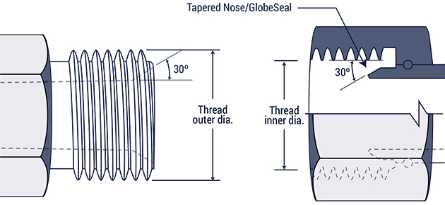
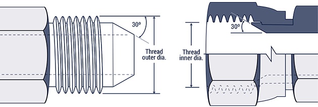
British Standard Pipe Parallel (BSPP) :
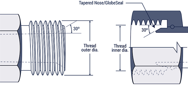 This connection has a male half with a 300 seat, and a female half with a rotating tapered nose, that forms the seal.
NOTE: The male connector may appear to look like the male American National Pipe Straight Mechanical, or NPSM; however, their thread pitches are not the same, and are not compatible.
| Inch size | Dash size | Thread Size | Male Thread O.D. (in) | Female thread O.D (in) | ||
| 1/8 | -2 | 1/8 - 28 | 3/8 | 0.38 | 11/32 | 0.35 |
| 1/4 | -4 | 1/4 - 19 | 33/64 | 0.52 | 15/32 | 0.47 |
| 3/8 | -6 | 3/8 - 19 | 21/32 | 0.65 | 19/32 | 0.60 |
| 1/2 | -8 | 1/2 - 14 | 13/16 | 0.82 | 3/4 | 0.75 |
| 5/8 | -10 | 5/8 - 14 | 7/8 | 0.88 | 13/16 | 0.80 |
| 3/4 | -12 | 3/4 - 14 | 1 1/32 | 1.04 | 31/32 | 0.97 |
| 1 | -16 | 1 - 11 | 1 5/16 | 1.30 | 1 7/32 | 1.22 |
| 1 1/4 | -20 | 1 1/4 - 11 | 1 21/32 | 1.65 | 1 9/16 | 1.56 |
| 1 1/2 | -24 | 1 1/2 - 11 | 1 7/8 | 1.88 | 1 25/32 | 1.79 |
| 2 | -32 | 2 - 11 | 2 11/32 | 2.35 | 2 1/4 | 2.26 |
British Standard Pipe Tapered (BSPT) :
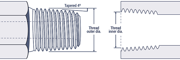 These are connectors where the seal is made between a tapered male and female thread.
NOTE: Although the BSPT male connector appears to look like the National Pipe Tapered Fuel, or NPTF; their thread size and form are not the same and therefore they are not compatible.
| Inch size | Dash size | Thread Size | Male Thread O.D. (in) | Female thread O.D (in) | ||
| 1/8 | -2 | 1/8 - 28 | 3/8 | 0.38 | 11/32 | 0.35 |
| 1/4 | -4 | 1/4 - 19 | 33/64 | 0.52 | 15/32 | 0.47 |
| 3/8 | -6 | 3/8 - 19 | 21/32 | 0.65 | 19/32 | 0.60 |
| 1/2 | -8 | 1/2 - 14 | 13/16 | 0.82 | 3/4 | 0.75 |
| 5/8 | -10 | 5/8 - 14 | 7/8 | 0.88 | 13/16 | 0.80 |
| 3/4 | -12 | 3/4 - 14 | 1 1/32 | 1.04 | 31/32 | 0.97 |
| 1 | -16 | 1 - 11 | 1 5/16 | 1.30 | 1 7/32 | 1.22 |
| 1 1/4 | -20 | 1 1/4 - 11 | 1 21/32 | 1.65 | 1 9/16 | 1.56 |
| 1 1/2 | -24 | 1 1/2 - 11 | 1 7/8 | 1.88 | 1 25/32 | 1.79 |
| 2 | -32 | 2 - 11 | 2 11/32 | 2.35 | 2 1/4 | 2.26 |
Flat Face Port with British Standard Pipe Parallel Threads (ISO 1179-1) :
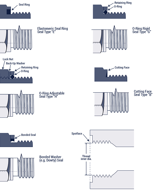 DIN 3852, Part 2
These connectors form their seal between the male half and the smooth surface of the female half, using a combination of rings or washers between their parallel threads.
Flat Face Port with Metric Threads (ISO 9974-1) :
DIN 3852, Part 1
These connectors form their seal between the male half and the smooth surface of the female half, using a combination of rings or washers between their parallel threads.
ISO 261 Metric threads
| Metric Thread Size | Male Thread O.D. (mm) | Female Thread I.D (mm) |
| M8 x 1.0 | 8 | 7 |
| M10 x 1.0 | 10 | 9 |
| M12 x 1.5 | 12 | 10.5 |
| M14 x 1.5 | 14 | 12.5 |
| M16 x 1.5 | 16 | 14.5 |
| M18 x 1.5 | 18 | 16.5 |
| M20 x 1.5 | 20 | 18.5 |
| M22 x 1.5 | 22 | 20.5 |
| M24 x 1.5 | 24 | 22.5 |
| M26 x 1.5 | 26 | 24.5 |
| M27 x 2.0 | 27 | 25 |
| M33 x 2.0 | 33 | 31 |
| M36 x 2.0 | 36 | 34 |
| M42 x 2.0 | 42 | 40 |
| M45 x 2.0 | 45 | 43 |
| M48 x 2.0 | 48 | 46 |
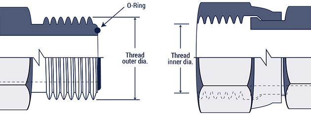
ISO 6149 Metric Port and Stud Ends :
 ISO 261 threads & O-ring seal
Connection with both male and female halves having straight threads. The female half has a smooth surface and a chamfer, and the male half has an O-ring. That O-ring compresses against the female chamfer to form the seal. . The male and female threads mesh to form a solid connection.
NOTE: Except for the metric threads on the ISO 6149, it connects in the same way as the SAE J1926-1O-ring Boss.
| Metric Thread Size | Male Thread O.D. (mm) | Female Thread I.D (mm) |
| M8 x 1.0 | 8 | 7 |
| M10 x 1.0 | 10 | 9 |
| M12 x 1.5 | 12 | 10.5 |
| M14 x 1.5 | 14 | 12.5 |
| M16 x 1.5 | 16 | 14.5 |
| M18 x 1.5 | 18 | 16.5 |
| M22 x 1.5 | 22 | 20.5 |
| M27 x 2.0 | 27 | 25 |
| M33 x 2.0 | 33 | 31 |
| M42 x 2.0 | 42 | 40 |
| M48 x 2.0 | 48 | 46 |
| M60 x 2.0 | 60 | 58 |
Metric 60° Cone :
DIN 7631
These connectors commonly found in hydraulic systems. The female connector has a globeseal seat, while the male has a 60° recessed cone (which forms the seal against the female's tapered nose). Both male and female have straight threads, that mesh to form a solid connection.
| Pipe/Tube O.D. (mm) | Metric Thread Size | Male Thread O.D. (mm) | Female Thread I.D (mm) |
| 6 | M12 x 1.5 | 12 | 10.5 |
| 8 | M14 x 1.5 | 14 | 12.5 |
| 10 | M16 x 1.5 | 16 | 14.5 |
| 12 | M18 x 1.5 | 18 | 16.5 |
| 15 | M22 x 1.5 | 22 | 20.5 |
| 18 | M26 x 1.5 | 26 | 24.5 |
| 22 | M30 x 1.5 | 30 | 28.5 |
| 28 | M38 x 1.5 | 38 | 36.5 |
| 35 | M45 x 1.5 | 45 | 43.5 |
| 52 | M52 x 1.5 | 52 | 50.5 |
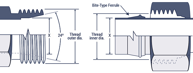
Metric Compression Fittings (DIN 2353 24° Cone) :
") Both male and female connectors have straight threads, with the male having a 240 cone, and the three female connectors a sealing surface. The 240 cone (male) and the sealing surfaces (females) form the seal.
Both male and female connectors have straight threads, with the male having a 240 cone, and the three female connectors a sealing surface. The 240 cone (male) and the sealing surfaces (females) form the seal.
There are two types of connectors - the DIN 2353 L light class, and the DIN 2353 S heavy class. The chart below lists tube sizes and thread dimensions for each class:
| DIN 2353 L Tube O.D.(mm) | DIN 2353 S Tube O.D. (mm) | Metric Thread Size | Male Thread O.D. (mm) | Female Thread I.D (mm) |
| 6 | M12 x 1.5 | 12 | 10.5 | |
| 8 | 6 | M14 x 1.5 | 14 | 12.5 |
| 10 | 8 | M16 x 1.5 | 16 | 14.5 |
| 12 | 10 | M18 x 1.5 | 18 | 16.5 |
| 12 | M20 x 1.5 | 20 | 18.5 | |
| 15 | 14 | M22 x 1.5 | 22 | 20.5 |
| 16 | M24 x 1.5 | 24 | 22.5 | |
| 18 | M26 x 1.5 | 26 | 24.5 | |
| 22 | 20 | M30 x 2.0 | 30 | 28 |
| 28 | 25 | M36 x 2.0 | 36 | 34 |
| 30 | M42 x 2.0 | 42 | 40 | |
| 35 | M45 x 2.0 | 45 | 43 | |
| 42 | 38 | M52 x 2.0 | 52 | 50 |

| Inch size | Dash size | Thread Size | Male Thread O.D. (in) | Female thread O.D (in) | ||
| 1/8 | -2 | 1/8 - 28 | 3/8 | 0.38 | 11/32 | 0.35 |
| 1/4 | -4 | 1/4 - 19 | 33/64 | 0.52 | 15/32 | 0.47 |
| 3/8 | -6 | 3/8 - 19 | 21/32 | 0.65 | 19/32 | 0.60 |
| 1/2 | -8 | 1/2 - 14 | 13/16 | 0.82 | 3/4 | 0.75 |
| 5/8 | -10 | 5/8 - 14 | 7/8 | 0.88 | 13/16 | 0.80 |
| 3/4 | -12 | 3/4 - 14 | 1 1/32 | 1.04 | 31/32 | 0.97 |
| 1 | -16 | 1 - 11 | 1 5/16 | 1.30 | 1 7/32 | 1.22 |
| 1 1/4 | -20 | 1 1/4 - 11 | 1 21/32 | 1.65 | 1 9/16 | 1.56 |
| 1 1/2 | -24 | 1 1/2 - 11 | 1 7/8 | 1.88 | 1 25/32 | 1.79 |
| 2 | -32 | 2 - 11 | 2 11/32 | 2.35 | 2 1/4 | 2.26 |
| Dash Size | Metric Thread Size | Male Thread O.D. (mm) | Female Thread I.D (mm) |
| -6 | M18 x 1.5 | 18 | 16.5 |
| -8 | M22 x 1.5 | 22 | 20.5 |
| -10 | M24 x 1.5 | 24 | 22.5 |
| -12 | M30 x 1.5 | 30 | 28.5 |
| -16 | M33 x 1.5 | 33 | 31.5 |
| -20 | M36 x 1.5 | 36 | 34.5 |
| -24 | M42 x 1.5 | 42 | 40.5 |
| Inch size | Dash size | Threads per Inch | Male Thread O.D. (in) | Female thread O.D (in) | ||
| 1/8 | -2 | 27 | 13/32 | 0.41 | 3/8 | 0.38 |
| 1/4 | -4 | 18 | 17/32 | 0.54 | 1/2 | 0.49 |
| 3/8 | -6 | 14 | 11/16 | 0.68 | 5/8 | 0.63 |
| 1/2 | -8 | 14 | 27/32 | 0.84 | 25/32 | 0.77 |
| 3/4 | -12 | 14 | 1 1/16 | 1.05 | 1 | 0.98 |
| 1 | -16 | 11 1/2 | 1 5/16 | 1.32 | 1 1/4 | 1.24 |
| 1 1/4 | -20 | 11 1/2 | 1 21/32 | 1.66 | 1 19/32 | 1.58 |
| 1 1/2 | -24 | 11 1/2 | 1 29/32 | 1.90 | 1 13/16 | 1.82 |
| 2 | -32 | 11 1/2 | 2 3/8 | 2.38 | 2 5/16 | 2.30 |
National Pipe Straight Mechanical (NPSM) :
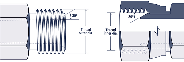 A connection where the male thread (with a 300 internal chamfer), and female thread (with an inverted 300 seat), are both straight. When the two are threaded together, the tapered seat forms a leak-resistant connection. These connections are used widely across fluid power systems.
NOTE: A NPSM female and a chamfered NPTF male can form a seal together.
| Inch size | Dash size | Threads per Inch | Male Thread O.D. (in) | Female thread O.D (in) | ||
| 1/8 | -2 | 27 | 13/32 | 0.41 | 3/8 | 0.38 |
| 1/4 | -4 | 18 | 17/32 | 0.54 | 1/2 | 0.49 |
| 3/8 | -6 | 14 | 11/16 | 0.68 | 5/8 | 0.63 |
| 1/2 | -8 | 14 | 27/32 | 0.84 | 25/32 | 0.77 |
| 3/4 | -12 | 14 | 1 1/16 | 1.05 | 1 | 0.98 |
| 1 | -16 | 11 1/2 | 1 5/16 | 1.32 | 1 1/4 | 1.24 |
| 1 1/4 | -20 | 11 1/2 | 1 21/32 | 1.66 | 1 19/32 | 1.58 |
| 1 1/2 | -24 | 11 1/2 | 1 29/32 | 1.90 | 1 13/16 | 1.82 |
| 2 | -32 | 11 1/2 | 2 3/8 | 2.38 | 2 5/16 | 2.30 |
JIC 37° Flare (SAE J514) :
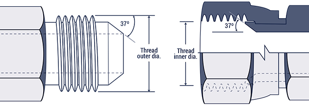 This connection is widely used in hydraulic systems, and both the male and female connectors have straight threads and a 37º flare seat. The straight threads of each half hold the connection together, sealing the flared seats.
NOTE: Most SAE J514 threads are exactly the same as the SAE 45º flare threads, however their seating angles differ.
| Inch size | Dash size | Thread Size | Male Thread O.D. (in) | Female thread O.D (in) | ||
| 1/8 | -2 | 5/16 - 24 | 5/16 | 0.31 | 9/32 | 0.27 |
| 3/16 | -3 | 3/8 - 24 | 3/8 | 0.38 | 11/32 | 0.34 |
| 1/4 | -4 | 7/16 - 20 | 7/16 | 0.44 | 13/32 | 0.39 |
| 5/16 | -5 | 1/2 - 20 | 1/2 | 0.50 | 15/32 | 0.45 |
| 3/8 | -6 | 9/16 - 18 | 9/16 | 0.56 | 17/32 | 0.51 |
| 1/2 | -8 | 3/4 - 16 | 3/4 | 0.75 | 11/16 | 0.69 |
| 5/8 | -10 | 7/8 - 14 | 7/8 | 0.88 | 13/16 | 0.81 |
| 3/4 | -12 | 1 1/16 - 12 | 11/16 | 1.06 | 1 | 0.98 |
| 7/8 | -14 | 1 3/16 - 12 | 1 3/16 | 1.19 | 1 1/8 | 1.10 |
| 1 | -16 | 1 5/16-12 | 1 5/16 | 1.31 | 1 1/4 | 1.23 |
| 1 1/4 | -20 | 1 5/8 - 12 | 1 5/8 | 1.63 | 1 9/16 | 1.54 |
| 1 1/2 | -24 | 1 7/8 - 12 | 1 7/8 | 1.88 | 1 13/16 | 1.79 |
| 2 | -32 | 2 1/2 - 12 | 2 1/2 | 2.50 | 2 7/16 | 2.42 |
SAE 45° Flare (SAE J512) :
 Typically used with low pressure systems like refrigerant lines, fuel lines, and automotive applications, the SAE male and female connectors similarly have a 45° flare seat which forms the seal. The threads of both halves mesh together for a strong mechanical connection. The SAE 45° Flare connectors are exactly the same as the JIC 37° Flare connectors, however their seating angles differ.
| Inch size | Dash size | Thread Size | Male Thread O.D. (in) | Female thread O.D (in) | ||
| 1/8 | -2 | 5/16 - 24 | 5/16 | 0.31 | 9/32 | 0.27 |
| 3/16 | -3 | 3/8 - 24 | 3/8 | 0.38 | 11/32 | 0.34 |
| 1/4 | -4 | 7/16 - 20 | 7/16 | 0.44 | 13/32 | 0.39 |
| 5/16 | -5 | 1/2 - 20 | 1/2 | 0.50 | 15/32 | 0.45 |
| 3/8 | -6 | 5/8 - 18 | 5/8 | 0.63 | 9/16 | 0.57 |
| 1/2 | -8 | 3/4 - 16 | 3/4 | 0.75 | 11/16 | 0.69 |
| 5/8 | -10 | 7/8 - 14 | 7/8 | 0.88 | 13/16 | 0.81 |
| 3/4 | -12 | 1 1/16 - 14 | 11/16 | 1.06 | 1 | 0.99 |
| 7/8 | -14 | 1 1/4 - 12 | 1 1/4 | 1.25 | 1 5/32 | 1.16 |
| 1 | -16 | 1 3/8 - 12 | 1 3/8 | 1.38 | 1 9/32 | 1.29 |
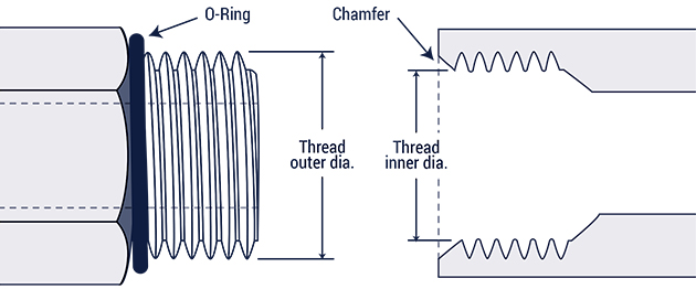
SAE Straight Thread O-ring (O-Ring Boss) :
 SAE J1926-1 and ISO 11296-1

A connection commonly found in high pressure hydraulic systems. While both halves have straight threads, the female has a sealing face and chamfer, and the male has an O-ring which when compressed into the opposing chamfer, forms the seal. The male and female threads mesh to form a solid connection.
| Inch size | Dash size | Thread Size | Male Thread O.D. (in) | Female thread O.D (in) | ||
| 1/8 | -2 | 5/16 - 24 | 5/16 | 0.31 | 9/32 | 0.27 |
| 3/16 | -3 | 3/8 - 24 | 3/8 | 0.38 | 11/32 | 0.34 |
| 1/4 | -4 | 7/16 - 20 | 7/16 | 0.44 | 13/32 | 0.39 |
| 5/16 | -5 | 1/2 - 20 | 1/2 | 0.50 | 15/32 | 0.45 |
| 3/8 | -6 | 9/16 - 18 | 9/16 | 0.56 | 17/32 | 0.51 |
| 1/2 | -8 | 3/4 - 16 | 3/4 | 0.75 | 11/16 | 0.69 |
| 5/8 | -10 | 7/8 - 14 | 7/8 | 0.88 | 13/16 | 0.81 |
| 3/4 | -12 | 1 1/16 - 12 | 11/16 | 1.06 | 1 | 0.98 |
| 7/8 | -14 | 1 3/16 - 12 | 1 3/16 | 1.19 | 1 1/8 | 1.10 |
| 1 | -16 | 1 5/16 - 12 | 1 5/16 | 1.31 | 1 1/4 | 1.23 |
| 1 1/4 | -20 | 1 5/8 - 12 | 1 5/8 | 1.63 | 1 9/16 | 1.54 |
| 1 1/2 | -24 | 1 7/8 - 12 | 1 7/8 | 1.88 | 1 13/16 | 1.79 |
| 2 | -32 | 2 1/2 - 12 | 2 1/2 | 2.50 | 2 7/16 | 2.42 |
Compression Tube Fittings (SAE J514) :
 The female connector includes a compression sleeve, a female nut, and a tube. The male connector has a 240 seat, which makes the seal with the female compression sleeve (the seal forms on the female side between the tubing and the compression sleeve). With non-flared tube fittings with straight threads, the male and female threads mesh to form a solid connection.
| Inch size | Dash size | Thread Size | Male Thread O.D. (in) | Female thread O.D (in) | ||
| 1/8 | -2 | 5/16 - 24 | 5/16 | 0.31 | 9/32 | 0.27 |
| 3/16 | -3 | 3/8 - 24 | 3/8 | 0.38 | 11/32 | 0.34 |
| 1/4 | -4 | 7/16 - 20 | 7/16 | 0.44 | 13/32 | 0.39 |
| 5/16 | -5 | 1/2 - 20 | 1/2 | 0.50 | 15/32 | 0.45 |
| 3/8 | -6 | 9/16 - 18 | 9/16 | 0.56 | 17/32 | 0.51 |
| 1/2 | -8 | 3/4 - 16 | 3/4 | 0.75 | 11/16 | 0.69 |
| 5/8 | -10 | 7/8 - 14 | 7/8 | 0.88 | 13/16 | 0.81 |
| 3/4 | -12 | 1 1/16 - 12 | 11/16 | 1.06 | 1 | 0.98 |
| 7/8 | -14 | 1 3/16 - 12 | 1 3/16 | 1.19 | 1 1/8 | 1.10 |
| 1 | -16 | 1 5/16 - 12 | 1 5/16 | 1.31 | 1 1/4 | 1.23 |
| 1 1/4 | -20 | 1 5/8 - 12 | 1 5/8 | 1.63 | 1 9/16 | 1.54 |
| 1 1/2 | -24 | 1 7/8 - 12 | 1 7/8 | 1.88 | 1 13/16 | 1.79 |
| 2 | -32 | 2 1/2 - 12 | 2 1/2 | 2.50 | 2 7/16 | 2.42 |
O-Ring Face Seal (SAE J1453) :
 These fittings join to form a highly leak resistive connection, in applications up to 6000 psi. Both halves have a straight thread, with the female having a flat surface and the male connector containing an O-ring. The seal is made when the O-ring on the male compresses against the flat surface of the female. The outside nut on the female connector holds the connection together.
| Inch size | Dash size | Thread Size | Male Thread O.D. (in) | Female thread O.D (in) | ||
| 1/4 | -4 | 9/16 - 18 | 9/16 | 0.56 | 17/32 | 0.51 |
| 3/8 | -6 | 11/16 - 16 | 11/16 | 0.69 | 5/8 | 0.63 |
| 1/2 | -8 | 13/16 - 16 | 13/16 | 0.82 | 3/4 | 0.75 |
| 5/8 | -10 | 1 - 14 | 1 | 1.00 | 15/16 | 0.93 |
| 3/4 | -12 | 1 3/16 - 12 | 13/16 | 1.19 | 1 1/8 | 1.11 |
| 1 | -16 | 1 7/16 - 12 | 1 7/16 | 1.44 | 1 3/4 | 1.36 |
| 1 1/4 | -20 | 1 11/16 - 12 | 1 11/16 | 1.69 | 1 5/8 | 1.61 |
| 1 1/2 | -24 | 2-12 | 2 | 2.00 | 1 15/16 | 1.92 |
SAE Inverted Flare (SAE J512) :
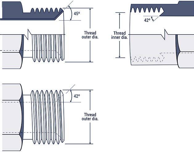 These connectors are widely used in the automotive industry. With the flared male tubing having a 450 seat, and the machined connector a 420 seat, the sealing surface is formed with the 420 seat on the end of the flare of the female connector. The male and female threads mesh to form a solid connection.
| Inch size | Dash size | Thread Size | Male Thread O.D. (in) | Female thread O.D (in) | ||
| 1/8 | -2 | 5/16 - 28 | 5/16 | 0.31 | 9/32 | 0.27 |
| 3/16 | -3 | 3/8 - 24 | 3/8 | 0.38 | 11/32 | 0.34 |
| 1/4 | -4 | 7/16 - 24 | 7/16 | 0.44 | 13/32 | 0.39 |
| 5/16 | -5 | 1/2 - 20 | 1/2 | 0.50 | 15/32 | 0.45 |
| 3/8 | -6 | 5/8 - 18 | 5/8 | 0.63 | 9/16 | 0.57 |
| 7/16 | -7 | 11/16 - 18 | 11/16 | 0.69 | 5/8 | 0.63 |
| 1/2 | -8 | 3/4 - 18 | 3/4 | 0.75 | 23/32 | 0.70 |
| 5/8 | -10 | 7/8 - 18 | 7/8 | 0.88 | 13/16 | 0.81 |
| 3/4 | -12 | 1 1/16 - 16 | 1 1/16 | 1.06 | 1 | 1.00 |
Four-Bolt Flange (SAE J518 and ISO 6162) :
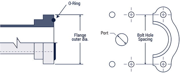 These commonly used in fluid power systems, and suitable for joining 1/2" - 3" hose or tube. The seal forms between the flat surface of the female port and the O-ring of the male (seated in the ring groove). A split clamp, using 4 bolts, hold the male/female together.
Note that there are two types of SAE J518 flanges available: standard pressure (code 61), and high pressure (code 62).
| Inch size | Dash size | Code 61 Bolt Spacing | Code 61 Flange O.D. | Code 62 Bolt Spacing | Code 62 Flange O.D. |
| 1/2 | -8 | 1 1/2 | 1 3/16 | 1 19/32 | 1 1/4 |
| 3/4 | -12 | 1 7/8 | 1 1/2 | 2 | 1 5/8 |
| 1 | -16 | 2 1/16 | 1 3/4 | 2 1/4 | 1 7/8 |
| 1 1/4 | -20 | 2 5/16 | 2 | 2 5/8 | 2 1/8 |
| 1 1/2 | -24 | 2 3/4 | 2 3/8 | 3 1/8 | 2 1/2 |
| 2 | -32 | 3 1/16 | 2 13/32 | 3 13/16 | 3 1/8 |
| 2 1/2 | -40 | 3 1/2 | 3 5/16 | n/a | n/a |
| 3 | -48 | 4 3/16 | 4 | n/a | n/a |
| Inch size | Dash size | Male Thread | Female thread | ||
| Thread size | Thread O.D. | Thread size | Thread I.D. | ||
| 3/8 | -6 | 5/8 - 18 | 5/8 | 5/8 - 18 | 9/16 |
| 1/2 | -8 | 3/4 - 18 | 3/4 | 3/4 - 16 | 11/16 |
| 5/8 | -10 | 7/8 - 18 | 7/8 | 7/8 - 14 | 13/16 |
| 3/4 | -12 | 1 1/16 - 16 | 1 1/16 | 1 1/16 - 14 | 1 |
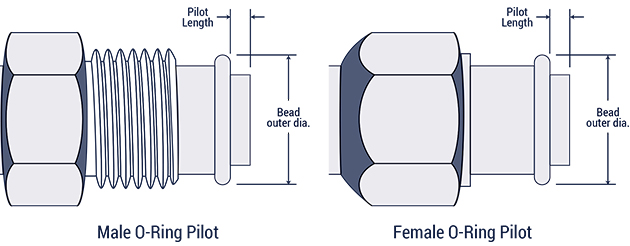
| Inch size | Dash size | Long pilot | Short pilot | ||
| Bead O.D. (in) | Pilot Length (in) | Bead O.D. (in) | Pilot Length (in) | ||
| 3/8 | -6 | 0.52 | 0.28 | 0.52 | 0.19 |
| 1/2 | -8 | 0.64 | 0.39 | 0.64 | 0.19 |
| 5/8 | -10 | 0.77 | 0.39 | 0.77 | 0.19 |
| 3/4 | -12 | 0.91 | 0.39 | 0.91 | 0.19 |